summoner12
Avid Member


I have been working on a way to solve my drainage issues. I hate shufling buckets around and spilling and forgetting... and having overflows.... and it can be a mess. 
So I came up with a few ideas and have been working on this for a while.
I started out wanting to have the water go into one bucket that I would dump. So I came up with a way to catch the water. I am using Coroplast. It is easy to cut and resembles cardboard, but made of plastic. I get it from work in 4'x8' sheets. I use hot glue to secure the pieces together.

Gussets, with slots for water to pass.
The table that catches the water is tilted forward but also on end is lower than the other... the rear side of the 'table' is level and the front two corners are offset. The right is about 2-3" lower than the rear and the left front corner is 1" lower than the right side. This causes the water to collect in one spot.
This is a 1" elbow with a 1/2" FIP fitting. I fit a 1/2" MIP to 1/3" tube adaptor onto the elbow fitting. The tubing then runs to my catch 'tub'.
I inject hot glue into the flutes of the Coroplast so water doesn't find it's way to the floor. I will be placing a screen over the opening to avoid clogging. In the racks with cages I should only be worried about dirt finding it's way down the tube... not a big deal. But with the free range I have to worry about bits of leaves, poop, urates, and larger bits or clumps of dirt.
I used 1/2" angled aluminum as the front support of the drainage table. The end fits nicely into the notches on the shelving up-right. With the zipties it doesn't take much to keep the piece from sliding down. It also makes it easier to determine the position the angled aluminum should be in. Since the up-right is marked, I just set the aluminum in one notch and then one notch lower on the other side .
.
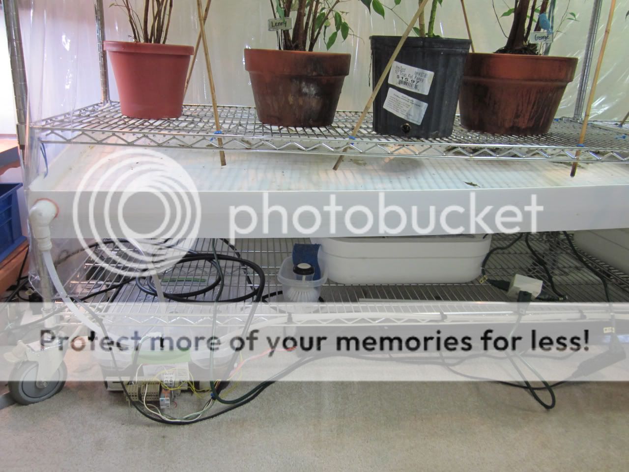
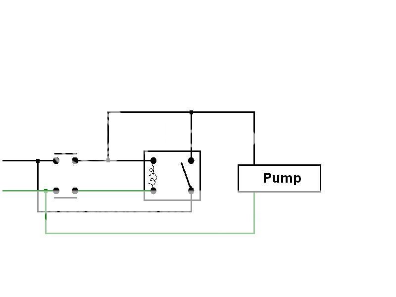
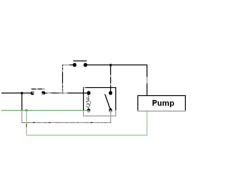
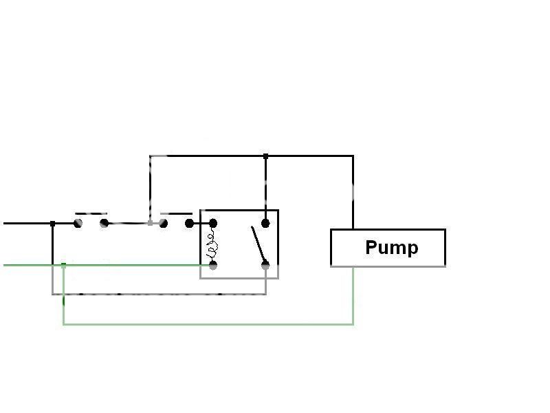
After attaching the hoses.... they will feed to my catch tub. The tub is fitting with float switches that will turn on and off a pump that empties the tub. When drilling my holes into the tub I made the 'empty' switch sit just above the drain fitting. While sitting on the throne it accered to me that I can set it lower because I can fit a tube onto the bulkhead fitting and place the end of the tube in the lowest spot on the tub to maximize the amount of water being removed. I was going to make a 'sump' inside of the tub so force the water to one side..... but now I don't have to. So in these photos of the switches the lower switch is no longer positioned as high, it is much lower.
This is a shot with the 'filler' that I was going to use. I was planning to inject 'great stuff' (that foam filler you inject in a hole through a wall along side of pipes) into the underside of the frame work for that piece I made. then trim the bits of foam that find their way out of the holes. Now, I don't have to worry about that and will be able to hold more water in the tub plus I don't have to go to HD and spend more money.
So I came up with a few ideas and have been working on this for a while.
I started out wanting to have the water go into one bucket that I would dump. So I came up with a way to catch the water. I am using Coroplast. It is easy to cut and resembles cardboard, but made of plastic. I get it from work in 4'x8' sheets. I use hot glue to secure the pieces together.


Gussets, with slots for water to pass.

The table that catches the water is tilted forward but also on end is lower than the other... the rear side of the 'table' is level and the front two corners are offset. The right is about 2-3" lower than the rear and the left front corner is 1" lower than the right side. This causes the water to collect in one spot.

This is a 1" elbow with a 1/2" FIP fitting. I fit a 1/2" MIP to 1/3" tube adaptor onto the elbow fitting. The tubing then runs to my catch 'tub'.

I inject hot glue into the flutes of the Coroplast so water doesn't find it's way to the floor. I will be placing a screen over the opening to avoid clogging. In the racks with cages I should only be worried about dirt finding it's way down the tube... not a big deal. But with the free range I have to worry about bits of leaves, poop, urates, and larger bits or clumps of dirt.


I used 1/2" angled aluminum as the front support of the drainage table. The end fits nicely into the notches on the shelving up-right. With the zipties it doesn't take much to keep the piece from sliding down. It also makes it easier to determine the position the angled aluminum should be in. Since the up-right is marked, I just set the aluminum in one notch and then one notch lower on the other side
.

After attaching the hoses.... they will feed to my catch tub. The tub is fitting with float switches that will turn on and off a pump that empties the tub. When drilling my holes into the tub I made the 'empty' switch sit just above the drain fitting. While sitting on the throne it accered to me that I can set it lower because I can fit a tube onto the bulkhead fitting and place the end of the tube in the lowest spot on the tub to maximize the amount of water being removed. I was going to make a 'sump' inside of the tub so force the water to one side..... but now I don't have to. So in these photos of the switches the lower switch is no longer positioned as high, it is much lower.


This is a shot with the 'filler' that I was going to use. I was planning to inject 'great stuff' (that foam filler you inject in a hole through a wall along side of pipes) into the underside of the frame work for that piece I made. then trim the bits of foam that find their way out of the holes. Now, I don't have to worry about that and will be able to hold more water in the tub plus I don't have to go to HD and spend more money.

Last edited:


")